SystemVerilog Cheatsheet
Table of Contents
- 1. Compile/Run
- 2. Modules
- 3. Data Types and Values
- 4. Operations and Conditions
- 5. Synchronous logic and assignments (alwaysff)
- 6. Finite State Machines
- 7. Testbench
1. Compile/Run
1.1. TL;DR
cdto foldervlib workon first runvlog <filename>.svto compile all relevant .sv filesvsim <testbench-name>to run your file (usually a testbench)add wave sim:/<testbench-name>/uut/*- Run your simulation using either:
run <N>to run for <N> nanosecondsrun -allto automatically stop testbench when completed
vlogto recompile relevant modules as neededrestart -fto restart your simulation
To run .tcl scripts, use source <script-name>.tcl.
1.2. Detailed Explanation:
- Navigate to your project directory using
cd.
The path should:- Use these slashes: ’/’
- Use English characters
- Not have any spaces (alternatively, it use quotes “”)
- Create a ’work’ library using the command
vlib work.- This is supposedly mandatory.
- Only needs to be performed while running your project for the first time.
- Compile your .sv files using
vlog- If some files depend on modules from other files,
You will have to compile these files first.
- If some files depend on modules from other files,
You will have to compile these files first.
- When running testbench, recompile relevant modules as needed using
vlog- You only need to recompile the relevant modules.
- No need to recompile the testbench itself or any other modules.
2. Modules
2.1. Defining a module
- Everything you write in SystemVerilog must be inside a module.
A module is a fundemental building block that receives inputs and generates outputs.
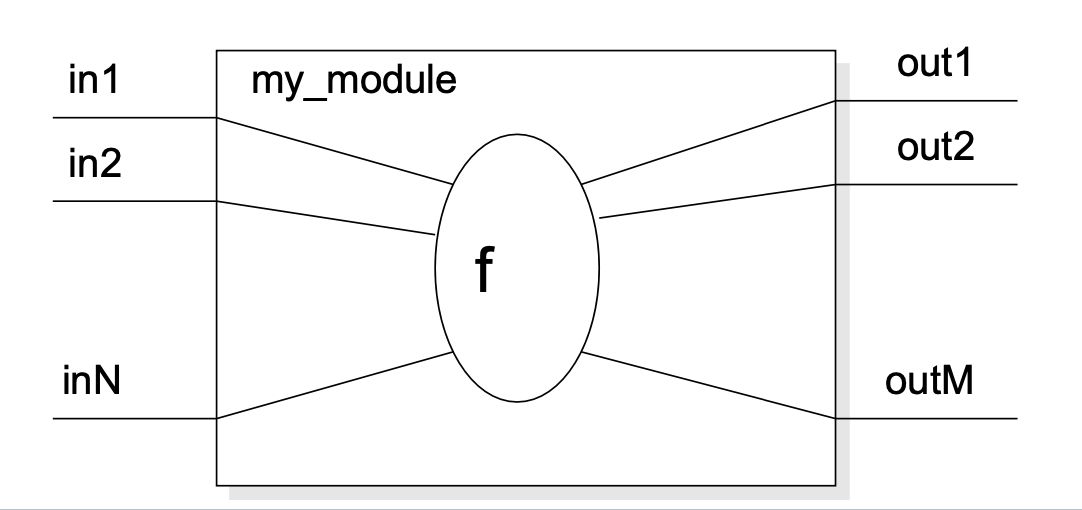
Here’s an example module:
// [a,b] -> [my_module] -> [result = (a AND b)]
module my_module(
   // Input and Output Declaration
   input logic  a,
   input logic  b,
   output logic result);
   // Declarations of "f"
    assign result = a & b;
endmodule
2.2. Creating module instances (instantiation)
2.2.1. Positional association
Define an instance of a module according to its argument positions, as such:
module_name instance_name (
    my_input1,
    ...,
    my_inputN,
    my_out1,
    ...,
    my_outM
);
2.2.2. Named association
Modules can also be instantiated using its arguments’ names explicitly:
module_name instance_name2 (
    .in1(my_input1)),
    ...,
    .inN(my_inputN),
    .out1(my_output1),
    ...,
    .outM(my_outputM)
)
2.3. Parameters
- Allows to pass parameters to a module per-instantiation.
- Note: different from logic inputs and outputs.
2.3.1. Definition inside a module declaration
module some_module (
    input logic in1
    output logic out1
);
   parameter param1 = 1; // 1 is a default value
   parameter param1 = 2;
   parameter param1 = 3;
endmodule
2.3.2. Usage when instantiating a module
A module that shifts a number left N times.
module shift_N (
    output logic [3:0] out,
    input logic [3:0] a
);
   parameter N = 1;
   always_comb begin
      out = a << N;
   end
endmodule
Here are some usage examples:
module multiple_shifts (
    input logic [3:0] a,
    output logic [3:0] b,
    output logic [3:0] c
);
   // Output a 2 shift result to b
   shift_N #(.N(2)) shift_2(.a(a), .out(b));

   // Output a 3 shift result to c
   shift_N #(.N(3)) shift_3(.a(a), .out(c));
endmodule
2.3.3. Local Parameters
Store constant values inside a module. These cannot be changed or passed to an instance module.
Here’s an example:
module my_module(...);
   localparam N = 2'b11;
   localparam NUM_OF_CYCLES = 10;
endmodule
2.4. Modules Inside Modules
2.4.1. Using modules inside other modules
// Mux that takes 2-bit inputs and outputs a 2-bit result
module mux2to1_2bit (
    output logic [1:0] O,
    input logic [1:0] A,
    input logic [1:0] B,
    input logic S
);
   // Use instances of existing 1-bit input muxes
   mux2to1_1bit mux1(.O(O[1]), .S(S), .A(A[1]), .B(B[1]));
   mux2to1_1bit mux0(.O(O[0]), .S(S), .A(A[0]), .B(B[0]));
endmodule
2.4.2. Generating many module instances at once (generate)
You can use the generate command to create many module instances at once:
module mux2to1_32bit (
    output logic [31:0] O, // 32-bit output
    input logic [31:0] A, // 32-bit input A
    input logic [31:0] B, // 32-bit input B
    input logic S
);
   genvar i;
   generate
      for (i = 0; i < 32; i++)
      begin
         mux2to1 mux_inst(.O(O[i]), .S(S), .A(A[i]), .B(B[i]));
      end
   endgenerate
endmodule
2.5. Concurrent assignment (השמה של ערכים מקבילים/ברי שינוי) to wires inside modules
Connect a wire to some combinatorical logic or another wire.
2.5.1. Syntax
// A simple assignment from one wire to another
module pass_same_value(
    output logic Z,
    input logic A
);
   assign Z = A;

endmodule

// Assigning some concurring calculation to wire
module and_module (
    output logic Z,
    input logic A,
    input logic B
);

   assign Z = A & B;
endmodule
An explicit value can also be used.
logic signal;
assign signal = 1'b0;
2.6. Procedular Blocks (הרצה סדרתית של הצהרות בתוך מודול)
2.6.1. Definition and types
All statements inside a procedural block are executed sequentially.
There are two procedural constructs in Verilog:
initialalways_combWe will only use
initialin simulations (testbenches). For regular modules, we usealways_comb.
2.6.2. alwayscomb
Executes statements in a loop. Used for combinatorical logic implementation.
Here’s a working example:
module and_module(
    output logic Z,
    input logic A,
    input logic B
);
   always_comb begin
      Z = A & B;
    end
endmodule
You can use conditional statements inside of a procedural block.
2.6.3. Complete assignments
Note: always_comb should NOT be used for memory elements!
- If a signal is not assigned in a certain flow, a memory element is implicitly created to preserve the previous value.
- Usually, this is a bug.
- Always use complete assignments.
3. Data Types and Values
3.1. SystemVerilog Logic Values
In SystemVerilog, a bit can take the following logical values:
| Logic Value | Meaning |
|---|---|
| 0 | zero / logic low / false / ground |
| 1 | one / logic high / true / power |
| x | not initialized or collision |
| z | unconnected |
3.2. 1-bit wires (logic)
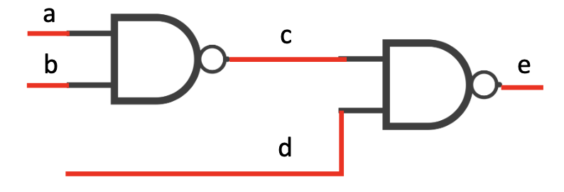
The logic data type represents a wire (1 bit):
logic a,b,c,d,e;
3.3. Vectors
Declaration of an 8-bit logic vector:
logic [7:0] w1; //w1[7] is the MSB
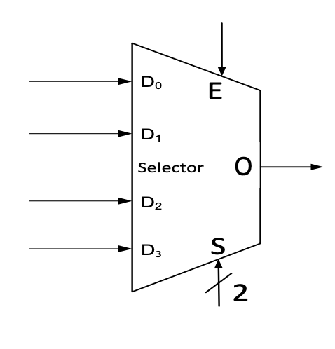
Here’s how you’d describe the “selector” wires in a mux module declaration:
module mux4tol(
               output logic O,
               input logic D0,
               input logic D1,
               input logic D2,
               input logic D3,
               input logic E,
               input logic [1:0] S
);
   // declarations
   // description of a mux
endmodule
3.3.1. Vector Operations
Bit select:
w1[3]Range select:
w1[3:2]
Pack:
vec = {x, y, z};Unpack:
{carry, sum} = vec[1:0];
3.3.2. Repeated Signals
A signal can be repeated \(n\) times in this manner:
vec = {16{x}} // 16 copies of x
3.3.3. A Working Example (Implementing Unsigned Extension)
logic [7:0] out;
logic [3:0] A;
out = {{4{1'b0}}, A[3:0]};
3.4. Integer Literals
Format: <width’><signed><radix> value
You can use this format to generate:
- Multiple bit integers (
<width'>) - Two’s complement negative numbers (
<signed>) - Write a number in base 2,8,10 or 16 (
<radix>)
3.4.1. Available number bases (<radix> values)
- Binary (
borB) - Octal (
oorO) - Decimal (
dorD) - Hexadecimal (
gorG)
3.4.2. Default settings
- Width = 32
- Unsigned
- Radix = Decimal
3.4.3. Examples
1'b0- one bit, unsigned, value of zero12'hAD1- 12 bits, unsigned, value of 0xAD112'b1010_1101_0001- 12 bits, unsigned, value of 0xAD114- defaults: 32 bits, unsigned, value of 14-14- 32 bits, signed, value of -14
3.5. Blocking and non-blocking assignment
3.5.1. Blocking assignment
Acts much like in traditional programming languages. The whole statemnt is done before control passes on to the next statement.
In always_comb, we use a blocking assigment:
logic a, in;
always_comb begin
   a = in;
end
3.5.2. Non-blocking assignment
Evaluates all the right-hand sides for the current time unit. Assigns the left-hand sides at the end of the procedural block.
Basically, allows behavior of a shift register.
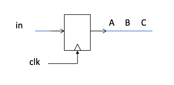
This is how you’d implement a shift behavior between Flip-Flops:
module shifter (
    input logic in,
    input logic clk
);
   logic A, B, C;

    always_ff @(posedge clk) begin
       A <= in;
       B <= A;
       C <= B;
    end
endmodule

And this is what happens when you accidentally use blocking assignments instead:
module bad_shifter (
    input logic in,
    input logic clk
);
   logic A, B, C;

    always_ff @(posedge clk) begin
       A = in;
       B = A;
       C = B;
    end
endmodule
3.6. enum
An enum type defines a set of named values.
We will use enum for FSM state declaration:
logic [7:0] out;
logic [3:0] A;
out = {{4{1'b0}}, A[3:0]};
typedef enum {idle_st, state1, state2} state_type;
4. Operations and Conditions
4.1. Logic Gates (built-in)
The following logic gates are available for direct instantiation:
- and
- or
- not
- xor
- nand
- nor
- xnor
Syntax:
gateName(output, input1, <optional_input2>)
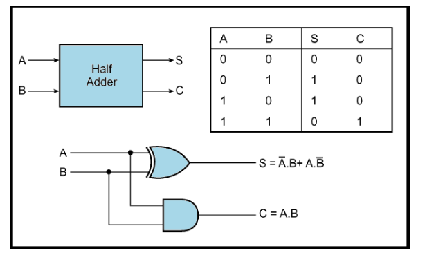
4.1.1. Example implementation of a half hadder
module HalfAdder (
    output logic S,
    output logic C,
    input logic A,
    input logic B
);
   xor(S, A, B);
   and(C, A, B);

endmodule
4.2. Operators (built-in)
4.2.1. Bitwise Operators
&- bitwise AND|- bitwise OR~- bitwise NOT^- bitwise XOR~^/^~- bitwise XNOR
4.2.2. Shift
>>- shift right<<- shift left
For example,
b = 4'b1010 << 2; // b = 4'b1000
c = 4'b1010 >> 1; // b = 4'b0101
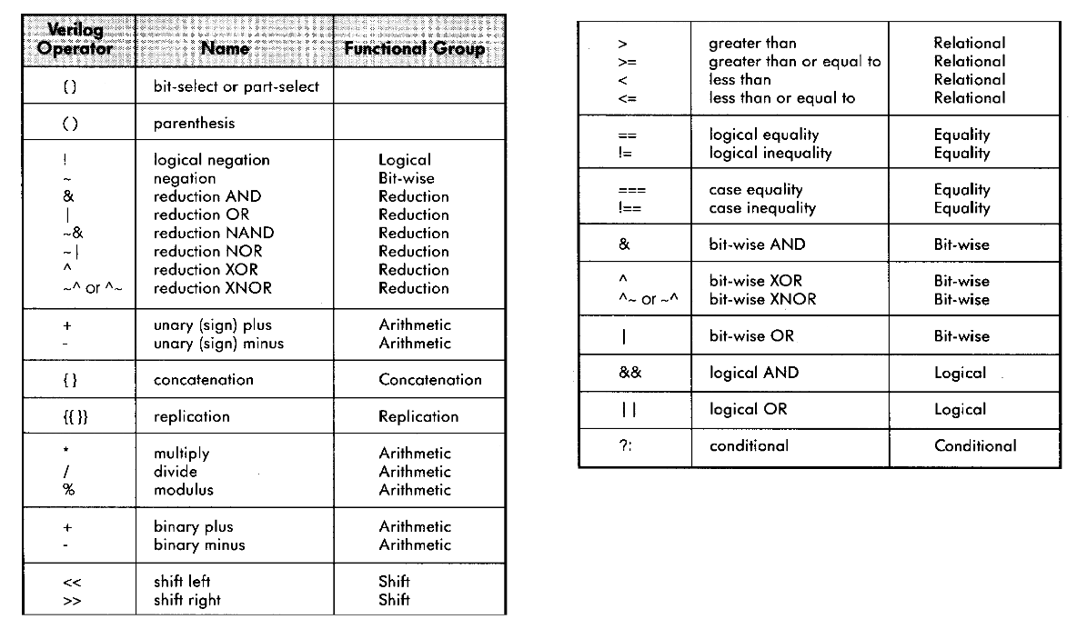
4.2.3. Operator Precedence
4.3. Logical Operators
4.3.1. Relational Operators
| Operator | Meaning |
|---|---|
| < | Less than |
| <= | Less than or equal to |
| > | Greater than |
| >= | Greater than or equal to |
| == | Equal to |
| != | Not equal to |
All of these return a 1-bit logical value (true/false/x)
4.3.2. Logical Operators
Used for conditions.
| Operator | Meaning |
| && | Logical AND |
| || | Logical OR |
| ! | Logical NOT |
- Operands evaluated to a 1-bit value: 0 (false), 1 (true) or x
- Result is a 1-bit value: 0 (false), 1 (true) or x.
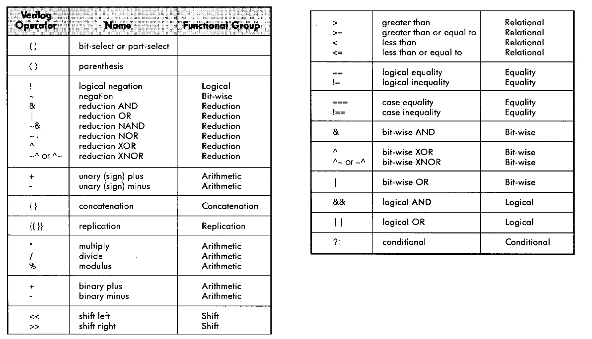
4.3.3. Operator Precedence
4.4. Conditional Statements
Used in procedural blocks.
4.4.1. if
- Syntax
if (condition1) begin
   <statement1>;
end
else if (condition2) begin
   <statement2>;
end
else begin
   <statement3>;
   <statement4>;
end
- A working example
module mux (
    input logic A,
    input logic B,
    input logic sel,
    output logic Q
);
   always_comb begin
      if (sel == 1'b0) begin
         Q = A;
      end
      else begin
         Q = B;
      end
    end
endmodule
4.4.2. case
- Syntax
case (<signal/expression>)
  <value1>: begin
     <statement1>;
  end
  <value2>: begin
     <statement2>;
  end
  default: begin
     <statement4>;
  end
endcase
- A working example
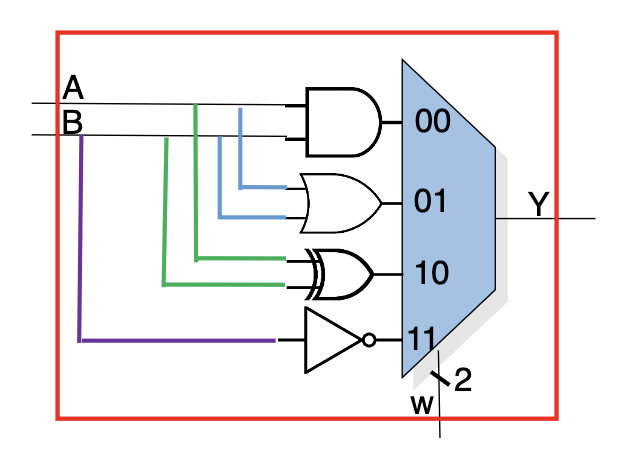
An example for mux behavior using
case.module case_example ( input logic A, input logic B, input logic [1:0] w, output logic Y ); always_comb begin case (w) 2'b00: Y = A & B; 2'b01: Y = A | B; 2'b10: Y = A ^ B; default: Y = ~B; endcase end endmodule
- casez
?andzare considered as don’t cares [0,1,z] - casex
?,xandzare considered as don’t cares [0,1,x,z]
5. Synchronous logic and assignments (alwaysff)
As opposed to always_comb, which implements an asynchronous/combinatorical block,
always_ff implements a synchronous block.
You usually want to use non-blocking assignments with alwaysff.
5.1. Positive Edge (דגימה בעליית שעון)
Using posedge, you can sample a value when your clock is on a positive edge.
This is an example that uses posedge to emulate a Flip-Flop:
logic a, in;
always_ff @(posedge clk) begin
   a <= in;
end
5.2. Synchronous Reset
Only occurs on positive edge. This is how you implement it:
always_ff @(posedge clk) begin
   if (rst == 1'b1) begin
      <reset statement1>;
   end
   else begin
      <sync statement2>;
   end
end
5.3. Asynchronous Reset
Can occur whenever the reset entrance rises. This is how you implement it:
always_ff @(posedge clk, posedge rst) begin
   if (rst == 1'b1) begin
      <reset statement1>;
   end
   else begin
      <sync statement2>;
   end
end
5.4. Implementing a Flip-Flop with Reset
This is how you implement a
6. Finite State Machines
6.1. FSM template
module my_FSM_module ( input logic input1, ... output logic outputN typedef enum { idle_st, start_st } sm_type; // Declaring signals for the next & current state sm_type current_state; sm_type next_state; // ... );
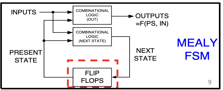
6.2. Next state recipe for synchronous logic
// FSM synchronous procedural block
always_ff @(posedge clk, posedge rst) begin
   if (rst == 1'b1) begin
      current_state <= idle_st;
   end
   else begin
      current_state <= next_state;
   end
end
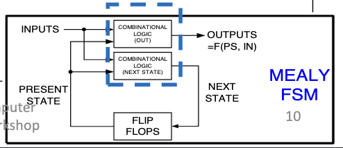
6.3. FSM - (Mealy) Asynchronous Logic
This is how you can use the current state to infer outputs and the next state:
always_comb begin
   // Default assignments
    next_state = current_state;
    output1 = 1'b0;
    ...
    outputN = 1'b0

    // Specific assignments
      case (current_state)
        idle_st: begin
           next_state = ...;
           ouput1 = ...;
           ...
           outputN = ...;
        end
        start_st: begin
           next_state = ...;
           output1 = ...;
           ...
           outputN = ...;
        end
        ...
      endcase
end
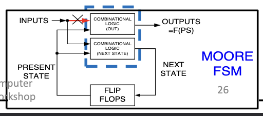
6.4. FSM - (Moore) Asynchronous Logic
always_comb begin
   case (current_state)
     S0_st: begin
        next_state = S1_st;
        z = 1'b0;
     end
     S1_st: begin
        next_state = S2_st;
        z = 1'b0;
     end
     S2_st: begin
        next_state = S0_st;
        z = 1'b1;
     end
     default: begin
        next_state = S0_st;
        z = 1'b0;
     end
end
7. Testbench
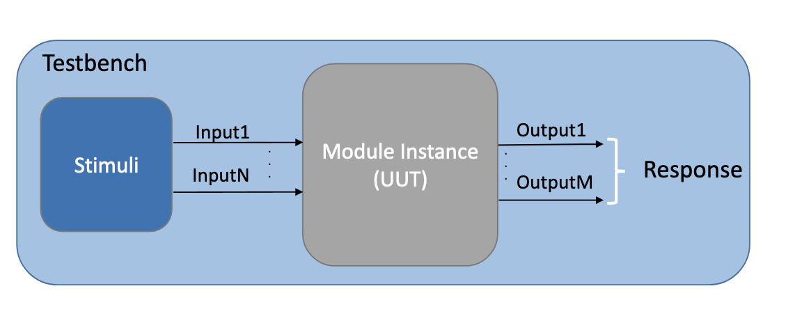
7.1. Unit Under Test (UUT)
A testbench generates input values and checks our Unit Under Test (UUT) for its response.
The UUT in our case is our module.
7.2. Generating input values
initial begin
   data = 0;
   #50 // Wait 50ns
   data = 1;
   #30 // Wait 30ns
   data = 0;
end
Here’s a working example:
// _tb stands for _testbench
module HalfAdder_tb;
   // Definition of testbench input values to UUT
   logic ha_a;
   logic ha_b;
   logic ha_sum;
   logic ha_carry;

   // Instance of UUT
   HalfAdder uut(
    .a(ha_a),
    .b(ha_b),
    .sum(ha_sum),
    .carry(ha_carry)
   );

   // Generate test input values here
   initial_begin
     ha_a = 0;
     ha_b = 0;

     #20
     ha_a = 1;
     ha_b = 0;

     #20
     ha_a = 1;
     ha_b = 1;
   end

endmodule
7.3. Repeat Loop
Used in an initial block to repeat statements.
repeat(num_of_times) begin
   <statement1>;
   <statement2>;
end
7.4. Synchronous logic: Generating a Clock Signal
This is how you generate a clock signal for simulation 2:
// Start value of clock
initial begin
   Clock = 1'b0;
end

// Clock behavior
always begin
   #10 Clock = ~Clock;
end
7.5. Synchronous logic: Wait X clock cycles
Example: Waiting for 4 clock cycles
initial begin
   repeat(4) begin
      @(posedge clk);
   end
end
7.6. How to Debug a FSM
- Always add the current and next state to the waveform
- Given the current state and the inputs, check that the next state and output are as expected
- As always, search for
xandzvalues and ensure they make sense
